The construction process and cost calculation of precast housing cannot be more detailed!
(Nuts shall be embedded on the precast wall to facilitate the oblique support fixation) After the oblique support is fixed, a seven-character code shall be installed at the bottom of the wall to strengthen the connection between the wall and the main structure, so as to ensure that the wall will not be displaced during subsequent operations.
Solid drawing of fixture (left) Side view of fixture (right) 4.
2.4.3 After the laminated plate is lowered to 0.5m from the floor, fine-tune it according to the pre-positioned guide frame and control line.
When the landing reaches 100mm, one worker uses a special visual mirror to observe whether the connecting reinforcement is aligned with the hole.
1.2 Scope of prefabrication The main structure of the project is a precast monolithic concrete shear wall structure, and the upper and lower walls are connected by sleeve grouting before.
Layout of precast components of standard floor 2.2.2 Preparation before lifting 1.
JGJ/T485-2019, will be implemented this year; This case deeply interprets the construction technology of precast components and the cost comparison analysis with traditional technology.
Schematic Diagram of Grouting Structure of Precast Wallboard 2.3.2 The outer edge of the joint shall be sealed after the completion of the warehouse division.
Project overview 1.1 Basic overview A project is located in a district of Wuhan City, covering an area of 68200 square meters, with a total planned building area of 327000 square meters, a total capacity building area of 229900 square meters, a building density of 38%, and a green space rate of 35%.
Set out the 1cm control line of the laminated plate surface.
The Technical Standard for Inspection of Fabricated Residential Buildings issued by the Ministry of Housing and Urban-Rural Development, No.
Site grouting operation 2.3.3 During grouting, the grouting surface shall be watered in advance without obvious water accumulation.
Snap out the wall side line and control line 3.
Before lifting the wall, the sealing strip shall be arranged at the wall edge, after lifting, the mortar shall be filled at the outer edge of the joint, the sealing strip shall be squeezed inward, and the formwork shall be fixed until the mortar is cured to the initial setting (not less than 24h) and can withstand the pressure of sleeve grouting before grouting.
Before grouting, the grouting hole shall be checked to ensure smoothness.
Through the horizontal joint connecting cavity, grout is poured into multiple sleeves at one time.
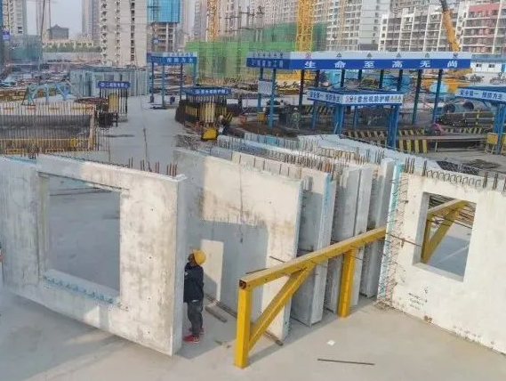
Each wall is installed with two adjustable diagonal supports and two seven-character codes.
The plot is divided into plot A and plot B, with plot A for commercial use and plot B for residential use, with a total area of 95000 square meters.
The proposed external wall hoisting sequence starts from YWQ23 on the south side of the main building, and the hoisting is carried out in a clockwise direction.
According to the sequence of grout discharge, rubber plugs (or cork plugs) are used to block the grout discharge holes in turn.
The hook shall not be removed before the final fixing of the diagonal support.
After the adjustment of the component is completed and the component positioning and elevation are checked to be correct, the hook shall be removed by a specially-assigned person.
Double diagonal bracing 2.3 grouting construction 2.3.1 Special construction scheme shall be prepared and special technical disclosure shall be conducted before sleeve grouting.
As it is difficult to deal with grout leakage during pressure grouting, joint sealing mortar and polyethylene rod sealing strip shall be used for sealing.
The grouting pump keeps the grouting pressure until all the upper holes of the sleeve have discharged the grout and are firmly blocked before stopping the grouting.
After the last grout outlet hole is blocked, the pressure shall be maintained for 5s to ensure the density of the grout in the sleeve.
The next picture of diagonal bracing installation (left) diagonal bracing and seven-character code installation diagram (right) seven-character code installation diagram can also be fixed by two diagonal bracing, and the seven-character code can be replaced by diagonal bracing.
2.
In case of slurry leakage, fill immediately.
Base treatment: the joint surface of the wallboard shall be cleaned and the base surface shall be dry.
The main precast members include precast external walls, precast floating windows, precast balconies, precast air conditioning panels, precast stairs, and precast laminated plates, with a prefabrication rate of more than 50%.
2.4 Laminate lifting process 2.4.1 Before lifting the laminated plate, measure and set out on the lower plate surface, and snap the dimension positioning line and the support upright positioning line; 2.4.2 A 1cm control line shall be set out at the overlap between the laminated plate and the precast or cast-in-place components; Set out the edge line of the laminated plate and the positioning line of the laminated plate frame.
Surveying and setting out: according to the positioning axis, snap the control line on the concrete roof of the working floor to install the wall in place, including the wall and the side line of the hole; 500mm elevation control line of the working floor (on the joint bar of the concrete floor); Center position line of sleeve.
After the fine-tuning is completed, slow down the lowering.
.
Two professional operators guide the landing by hand.
The corresponding grouting plugging, reinforcement works of cast-in-place wall columns and formwork works are carried out in this order.
The grouting method is used to grout from the lower hole of the sleeve.
Setting of wall elevation adjusting gasket: before installation of wallboard, shims shall be set between precast components and their supporting components for elevation adjustment and leveling.
Construction process flow of precast shear wall structure The main precast components of precast shear wall system include precast shear wall, precast floor slab, 2.1 measurement process flow, 2.2 precast wall hoisting process, 2.2.1 The standard floor structure of each main building is the same.
Prefabrication of horizontal members and above on the third floor begins.
Correction of exposed connecting reinforcement: check the perpendicularity, positioning and height of the reinforcement with self-made reinforcement fixture, and correct the reinforcement that does not meet the requirements to ensure that the sleeve on the upper precast outer wall and the reserved reinforcement on the next layer can be aligned smoothly.
(The lifting personnel on the working face shall adjust the position of the embedded reinforcement according to the component positioning line and elevation control line in advance, prepare the sizing block, place the component into the control line, and place the sizing block) Two professional operators shall guide the lowering by hand and observe the reinforcement through the hole with a special visual mirror 2.2.5 After the installation of the support system and the wall stops falling, a specially-assigned person shall install the diagonal support and the seven-character code, and use the diagonal support and the seven-character code to fix and adjust the precast wall, Ensure the verticality of wall installation.
Steel gasket leveling (left) embedded bolt leveling (right) 2.2.3 Precast wall lifting Fasten the special hook firmly on the hanging nail and slowly lift the outer wall to 0.5m high 2.2.4 Precast wall installation When the wall is lowered to 0.5m from the floor, fine-tune according to the pre-positioned guide frame and control line, and then slow down after fine-tuning.
The thickness of leveling layer is usually 20mm, and the leveling can use gaskets and embedded bolts.